Synchronisation
Experiments often require synchronising behavioural data with other systems such as video cameras or physiology recordings. pyControl provides several methods for data synchronisation between systems.
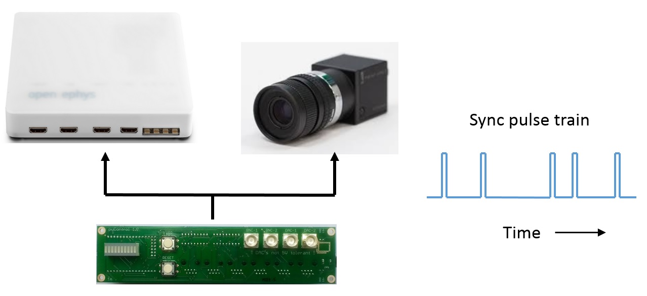
The recommended tool for synchronisation is called Rsync and works by outputting sync pulse trains with random inter-pulse intervals. The times when sync pulses occurred are recorded by each system in their own time reference frame and can then be used to convert times from one system into the reference frame of another using code provided in the rsync module in the tools folder. The random inter-pulse intervals ensure there is a unique match between the inter-pulse-interval sequences recorded on each system, so it is always possible to identify which pulse corresponds to which even if some pulses are missing, e.g. due to forgetting to turn a system on till after the start of a session. This also makes it unambiguous whether two files come from the same session in the event of a file name mix-up. The only functionality a system needs to be synchronised in this way is the ability to record when digital input pulses occurred. This can be by explicitly storing timestamps, or implicitly, such as camera recording once each frame the state of an input pin (or whether an LED in the field of view is on or off).
Regular sync pulses can be generated using the Frame_trigger class. This is not as robust to user or hardware error, as if pulses are missing it may not be possible to work out which pulse corresponds to which between systems, but can be useful for working with cameras where frame acquisition can be triggered by external inputs. The Frame_logger class can be used to record pulse times generated by another system with less overheads than using a standard Digital_input.
Some data acquisition systems record timestamps using the computer's clock. If you want to align data generated by such a system with pyControl data, you can use the start_time and end_time info rows in the pyControl datafile to get the computer clock datetimes corresponding to the start and end of the pyControl session. For accuracy, it is recommended to linearly interpolate the times of pyControl events between the session start and end time, rather than using only the start time, due to possible drift between the pyboard clock (which generates timestamps in the data file time column) and the computer clock. If using this approach it is recomended to run both pyControl and the other system on the same computer.
Sync pulse generation and logging
Rsync
The Rsync class is used to generate sync pulse trains with random inter-pulse intervals. A single Rsync should be used to synchronise all external systems, so that they all receive the same sync pulse train. This can be achieved by outputting the signal on one of the breakout board BNC connectors and using BNC T-junction adapters (e.g. this) to split the signal to the different systems. It is also possible to output the sync pulses on multiple outputs by passing in a list of pins. Sync pulse times are recorded in the pyControl data file using the specified event name. If an Rsync object is instantiated in the task or hardware definition, sync pulses will be generated automatically while the task is running as long as the event name is included in the task's events list.
class Rsync(pin, event_name='rsync', mean_IPI=5000, pulse_dur=50)
Arguments:
pin MicroPython pin to output sync pulses on, or a list of pins to output sync pulses on more than one output.
event_name Name of the sync pulse events in pyControl data output.
mean_IPI Mean interval between sync pulses (milliseconds). Inter-pulse intervals are drawn from a uniform distribution on the range 0.1*mean_IPI to 1.9*mean_IPI.
pulse_dur Sync pulse duration (milliseconds).
Example usage:
sync_output = Rsync(pin=board.BNC_1, mean_IPI=1000) # Instantiate Rsync object on breakout board BNC_1

sync_output = Rsync(pin=[board.BNC_1, board.BNC_2], mean_IPI=1000) # Instantiate Rsync object on breakout board BNC_1 & BNC_2
Frame_trigger
The Frame_trigger object is used to generate regular pulse trains at a specified frequency, and is designed for triggering camera frame acquisition or similar applications. The pulse train is a square wave with a 50% duty cycle and is output continuously while the framework is running. The time of pulse rising edges and corresponding pulse numbers are saved as .npy files (see the analog data docs).
class Frame_trigger(pin, pulse_rate, name='frame_trigger')
Arguments:
pin The pin to output pulses on.
pulse_rate The rate in Hz of the output pulse train.
name Name of the Frame_trigger object used to identify the datafile.
Example usage:
frame_trigger = Frame_trigger(pin=board.BNC_2, pulse_rate=60) # Instantiate Frame_trigger on breakout board BNC_2
Frame_logger
The Frame_logger can be used to record the times of sync pulses generated by annother system. The differences between the Frame_logger and a standard Digital_input are:
- Events generated by the
Frame_loggerare recorded in the data log but not processed by the task state machine, reducing load on the pyboard. - A
decimateargument can be used to only log one in every n events, useful with inputs that generate pulses at high rates. - Events recorded by the
Frame_loggerhave asyncrather thaninputsubtype (see pyControl data).
class Frame_logger(pin, rising_event, decimate=False, pull=None)
Arguments:
pin MicroPython pin to use
rising_event Name of event triggered on rising edges.
decimate Set to n to only generate one event every n pulses.
pull Set to 'up' or 'down' to enable internal pullup or pulldown resistor.
Example usage:
frame_logger = Frame_logger(pin=board.BNC_2, rising_event="camera_frame") # Instantiate Frame_logger on breakout board BNC_2
Synchronising data with Rsync
The rsync module in the tools folder can be used in Python to convert event times from one hardware system's reference frame to that of another system by using sync pulse times generated by the Rsync object recorded on both systems. To illustrate this, assume we have an array of sync pulse times recorded by pyControl called pulse_times_pycontrol and an array of sync pulse times recorded by an ephys system called pulse_times_ephys. We also have an array of spike times recorded by the ephys system called spike_times_ephys which we want to convert into the reference frame of the pyControl data. We first instantiate an Rsync_aligner object using the pulse times recorded by both systems:
from rsync import Rsync_aligner

ephys_aligner = Rsync_aligner(
    pulse_times_A=pulse_times_pycontrol,
    pulse_times_B=pulse_times_ephys,
)
We can then convert the spike times recorded by the ephys system into the pyControl data's time reference frame using:
spike_times_pycontrol = ephys_aligner.B_to_A(spike_times_ephys)
We could also convert an array of pyControl event times into the reference frame of the ephys data using:
event_times_ephys = ephys_aligner.A_to_B(event_times_pycontrol)
To work out which pulses correspond to which in the two sequences, the alignment code needs to know the relative units the two sets of pulse times are recorded in. For example, imagine we want to synchronise a camera which acquires frames at 60Hz with pyControl data, using an array called pulse_frame_numbers specifying the frame numbers when sync pulses occurred. The pyControl pulse times are in units of ms whereas the pulse_frame_numbers are in units of 1000/60 = 16.67ms. By default, the alignment code will automatically estimate the relative units from the pulse trains themselves. Alternatively you can explicitly specify the units for each pulse sequence in ms:
camera_aligner = Rsync_aligner(
    pulse_times_A=pulse_times_pycontrol,
    pulse_times_B=pulse_frame_numbers,
    units_A=1,
    units_B=1000 / 60,
)
Automatic detection of the units convenient but may fail to find a match between the pulse sequences if you have too few sync pulses to accurately estimate the mean inter-pulse interval. Specifying the units manually can also be a good sanity check to make sure the data are as expected, for example if the camera was actually acquiring frames at 100Hz rather than 60Hz, the error would be detected when specifying units manually because the sync code would not find a match between the pulse sequences.
We can then convert the frame numbers when an event of interest occurred into the pyControl data's time reference frame using:
frame_times_pycontrol = camera_aligner.B_to_A(video_frame_numbers)
We can also convert the times when a pyControl event occurred into the corresponding camera frame numbers:
event_frame_numbers = camera_aligner.A_to_B(event_times_pycontrol)
An example analysis showing how to synchronise pyControl behavioural data with neural activity recorded using pyPhotometry is provided in this data synchronisation jupyter notebook.
Rsync_aligner class reference
class Rsync_aligner(pulse_times_A, pulse_times_B, units_A='auto', units_B='auto',
            chunk_size=5, plot=False, raise_exception=True)
Arguments:
pulse_times_A The times when sync pulses occurred recorded by hardware system A.
pulse_times_B The times when sync pulses occurred recorded by hardware system B.
units_A The time units used by system A expressed in milliseconds. E.g. if system A uses units of seconds the units_A argument is 1000. If either units_A or units_B is set to the default value of 'auto' the code will automatically estimate the relative units for the two sequences from the pulse times themselves.
units_B The time units used by system B expressed in milliseconds.
chunk_size The length of pulse sequence chunks used for alignment, see below.
plot Whether to plot information about the alignment.
raise_exception If True an RsyncError exception is raised if no match is found between the sync pulse sequences. If False an error message is printed but no exception is raised.
Methods:
Rsync_aligner.A_to_B(event_times_A, extrapolate=True)
Convert a set of event times recorded by system A into the time reference frame of system B. If extrapolate is set to False then any event_times_A before the first matched sync pulse or after the last matched sync pulse will be converted to NaN, if extrapolate is True then the corresponding times in B reference frame will be estimated by linear extrapolation from the closest matched pulse time.
Rsync_aligner.B_to_A(event_times_B, extrapolate=True)
Convert a set of event times recorded by system B into the time reference frame of system A.
Implementation:
When the aligner is instantiated it works out which pulses from each system correspond to each other by taking short chunks of pulse sequence A and finding the corresponding chunks of pulse sequence B which minimise the mean squared error between the inter-pulse intervals. As the alignment is performed on short chunks rather than the whole sequence, it is robust against missing pulses on one or both systems even if they occur part way through a recording.
After finding for each chunk the match which minimises the mean squared error, the aligner determines a mean-squared error threshold which separates chunks that have a corresponding match in the other sequence from chunks that do not have a match (due to missing pulses). The threshold is found by fitting a mixture of Gaussians to the distribution of log mean squared errors from both the best matches and second best matches for all chunks. This distribution should have two well separated peaks, one containing correct matches and the other non-matches.
The A_to_B and B_to_A methods convert event times from the reference frame of one system to that of the other by linearly interpolating between sync pulse times on either side of the event. These functions return NaNs for any event time where the sync pulses on either side of the event do not have a match in the pulse sequence recorded on the other system.
If the plot argument is set to True when the aligner is instantiated, the following plots are generated:
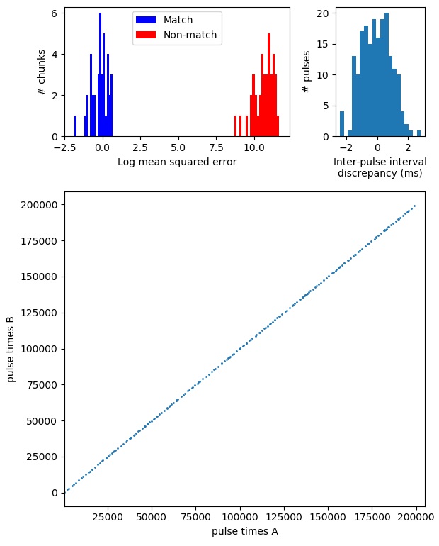
The top left panel shows the distribution of log mean squared error for the best and second best matches for all chunks, with colour indicating which are identified as matches and which non-matches. The top right panel shows the distribution of discrepancies between inter-pulse intervals recorded on the two systems. The bottom panel plots pulse times recorded by system A against corresponding pulse times recorded by system B.