Hardware
Overview
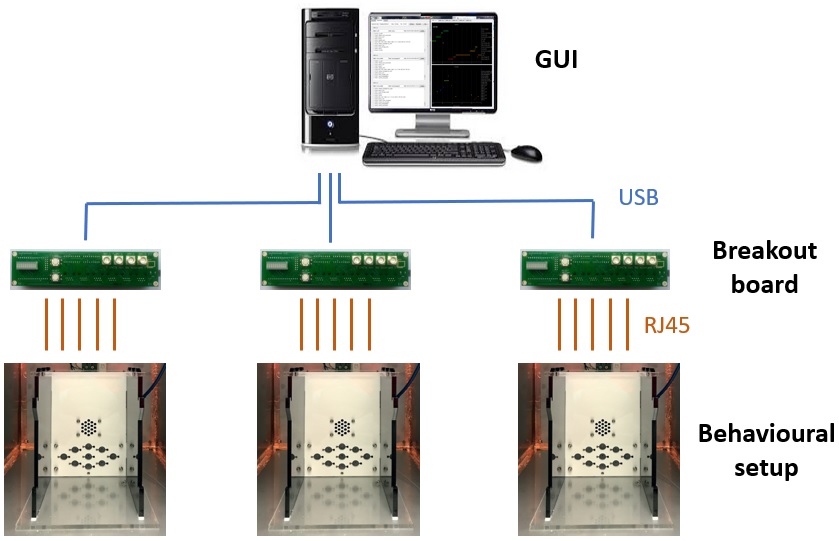
A typical pyControl hardware setup consists of one or more breakout boards connected to a computer by USB, each of which runs a single behavioural setup. The breakout board connects to a set of devices such as nosepokes, audio boards and LED drivers which make up the setup. USB hubs can be used between the computer and breakout boards such that many setups can be controlled from a single computer.
All pyControl hardware is open source, design files are in the hardware repository on GitHub. In addition to pyControl electronics, the repository has designs for a behaviour box and sound attenuating chamber, and a list of useful parts such as cables, solenoids, mounting hardware etc. for building setups. Assembled pyControl hardware is available from the Open Ephys store and LabMaker.
For information about synchronising pyControl with other hardware such as electrophysiology or video cameras see the synchronisation user guide.
Safety
Attention
As electronic devices, pyControl hardware could pose a fire risk if used inappropriately.
- All boards should be securely mounted using M3 bolts and insulating spacers to prevent short circuits due to contact with metal objects.
- Power down hardware when not in use.
- When connecting external devices consider the amount of current they will draw. See the Breakout boards section below for more information.
Hardware definitions
Hardware objects can be instantiated directly in a state machine definition file (as in the button example), however the recommended way of specifying hardware is to create a hardware definition file which is imported by the state machine. The rationale for this is twofold: Firstly, the same hardware setup is typically used for many different tasks so separating out the hardware and task definition code into separate files avoids repeating the hardware definition in each task file. Secondly, the same task may be used on different setups without modifying the task code as long as the required hardware devices are specified in the setup's hardware definitions.
The hardware definition tells the pyControl system what inputs and outputs are available for use by state machines. A simple hardware definition file might read:
from devices import *

button = Digital_input(pin='X1', rising_event='button_press')
LED    = Digital_output(pin='X2')
This specifies that there is a digital input called button connected to pin X1 on the pyboard, and a digital output called LED connected to pin X2. Each time a rising edge occurs on pin X1, a framework event named 'button_press' will be generated, you can also specify events to be generated when falling edges occur on digital inputs:
button = Digital_input(pin='X1', rising_event='button_press', falling_event='button_release')
By convention the hardware definition file is imported into state machine definitions with:
import hardware_definition as hw
such that hardware objects are accessed in the state machine definition as in the examples below:
hw.button.value() # Read the state of the button.

hw.LED.on()      # Turn the LED on

hw.LED.off()     # Turn the LED off
You can turn off all outputs (for example at the end of a session) using the command:
hw.off() # Turn off all outputs.
Inputs and outputs
The following hardware classes control the behaviour of a single pin on the MicroPython microcontroller.
Digital input
The digital input class generates pyControl framework events when a specified pin on the MicroPython board changes state. Seperate events can be specified for rising and/or falling edges.
By default, debouncing is used to prevent multiple events being triggered very close together in time if the edges are not clean. The debouncing method used ensures that transient inputs shorter than the debounce duration still generate rising and falling edges. Debouncing incurs some overheads so should be turned off for inputs with clean edges and high event rates.
class Digital_input(pin, rising_event=None, falling_event=None, debounce=5, pull=None)
Arguments:
pin MicroPython pin to use
rising_event Name of event triggered on rising edges.
falling_event Name of event triggered on falling edges.
debounce Minimum time interval between events (ms), set to False to deactive debouncing.
pull Set to 'up' or 'down' to enable internal pullup or pulldown resistor.
Methods:
Digital_input.value() Get the current state of the input, returns True if pin is high, False if low.
Digital output
The digital output class is used to control a pyboard pin used as a digital output.
class Digital_output(pin, inverted=False)
Arguments:
pin MicroPython pin to use.
inverted If True, the pin voltage is set high when the input is turned off and low when turned on.
Methods:
Digital_output.on() Turn on output.
Digital_output.off() Turn off output.
Digital_output.toggle() Toggle output.
Digital_output.pulse(freq, duty_cycle=50, n_pulses=False) Turn on a pulse train with specified frequency (Hz). The duty cycle (percentage of the period for which the signal is high) can be specified as any multiple of 5 betweeen 5 and 95. If the n_pulses argument is set to an integer the pulse train will stop after this number of pulses has been delivered.
Analog input
The analog input class measures the voltage on a pin at a specified sampling rate, streams these measurements to the host computer to be saved to disk, and can optionally generate pyControl framework events when the voltage rises above and/or falls below one or more specified thresholds.
The input voltage is measured with 12 bit resolution giving a number between 0 and 4095, corresponding to the voltage range 0 to 3.3V relative to the pyboard ground.
Acquiring analog data and streaming it to the host computer uses pyboard processor and communication resources, so attempting to acquire at too high sampling rates, or from too many inputs simultaneously, will overload the board. The maximum achievable sample rates have not been extensively tested, though six analog inputs acquiring at 1KHz each appears to work.
class Analog_input(pin, name, sampling_rate, threshold=None, rising_event=None, falling_event=None, triggers=None)
Arguments:
pin MicroPython pin to use. Only a subset of MicroPython pins support analog to digital conversion (ADC) (see pyboard quickref).
name Name of the analog input, used to identify data files generated when input is recorded.
sampling_rate The rate at which the pin voltage is sampled (Hz).
threshold Threshold against which voltage samples are compared for generating rising and falling events, must be an integer between 0 and 4095.
rising_event Name of event triggered when voltage crosses threshold in rising direction.
falling_event Name of event triggered when voltage crosses threshold in falling direction.
triggers Used to specify multiple thresholds for generating framework events by passing in a list of Analog_trigger objects (see below). If the triggers argument is used then the threshold, rising_event and falling_event arguments are ignored.
Example usage:
# Instantiate Analog_input on pin X1 with one event generating threshold.
analog_input_1 = Analog_input(pin='X1', name='Analog_1', sampling_rate=500, threshold=2000,
                              rising_event='rising_edge' , falling_event='falling_edge')
Analog trigger
A list of Analog_triggers can be used with an Analog_input to specify multiple thresholds that generate pyControl events when crossed the rising and/or falling direction.
class Analog_trigger(threshold=None, rising_event=None, falling_event=None)
Arguments have the same functionality as those for the analog input.
Example usage:
# Instantiate Analog_input on pin X2 with two event generating thresholds.
low_trigger  = Analog_trigger(threshold=1000, rising_event='rising_low' , falling_event='falling_low')
high_trigger = Analog_trigger(threshold=3000, rising_event='rising_high', falling_event='falling_high')
analog_input_2 = Analog_input(pin='X2', name='Analog_2', sampling_rate=1000,
                            triggers=[low_trigger, high_trigger])
Analog outputs
Pyboard pins 'X5' and 'X6' support analog output. On the breakout board they are connected to the BNC connectors labeled DAC-1 and DAC-2 and also to the special function pins on behaviour ports 3 and 4 respectively. To use these pins as analog outputs see the pyb.DAC class in the MicroPython docs.
Breakout boards
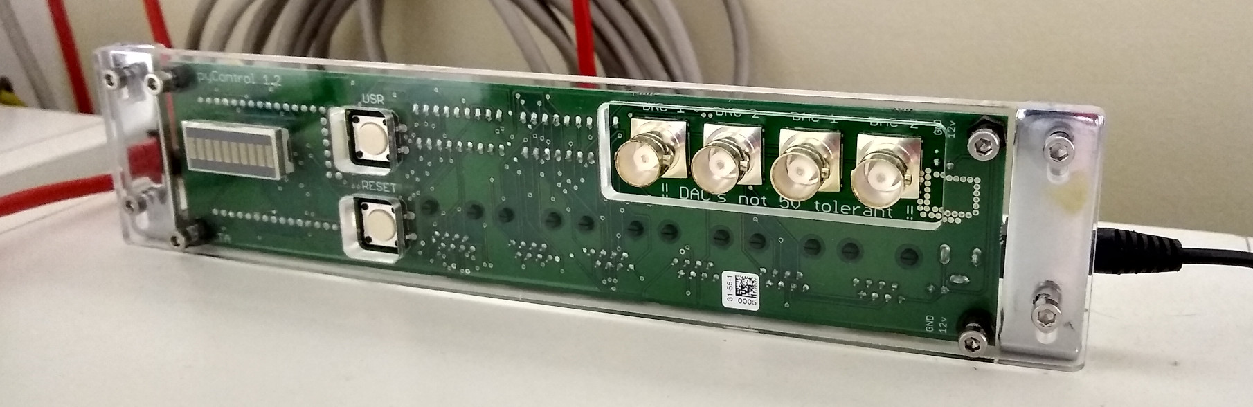
Typically, when pyControl is used to run a behavioural experiment, the pyboard microcontroller is mounted on a breakout board, which interfaces it with behaviour ports, BNC connectors, indicator LEDs and user pushbuttons.
The current version 1.2 of the pyControl Breakout board has 6 RJ45 behaviour ports, 4 BNC connectors, indicator LEDs and user pushbuttons.
The BNC connectors connect directly to pins on the microcontroller. All 4 BNC connectors can be used as digital inputs or outputs. When used as digital outputs they have a 3.3V high logic level, which can typically be used directly as an input for systems with 5V logic. When used as digital inputs, BNC-1 and BNC-2 work with 5V or 3.3V logic level input signals, but DAC-1 and DAC-2 are not 5V tolerant and should not be used with signals >3.3V. All 4 BNC connectors can also be used as analog inputs, but when used in this mode the input signal should not exceed 3.3V. Connectors DAC-1 and DAC-2 can also be used as analog ouputs.
See below for information about pinout and function of lines on the behaviour ports. On breakout board 1.2, all six behaviour ports have the standard 2 digital input/output (DIO) lines, 2 POW driver lines, and 5V, 12V and ground lines. Ports 1 & 2 have an additional driver line POW_C. Ports 3 and 4 have an additional DIO line DIO_C which also supports analog output (DAC). Ports 3 and 4 support I2C and ports 1,3 & 4 support UART serial communication over their DIO lines. Useful resources for understanding the additional functionallity of the lines on each port are the Schematic (PDF) and device definition file for the breakout board and the pyboard quick reference.
The hardware repository has designs for enclosures and brackets for mounting the breakout board PCB.
Schematic (PDF) GitHub, Open Ephys, LabMaker
Breakout 1.2 front:
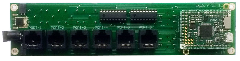
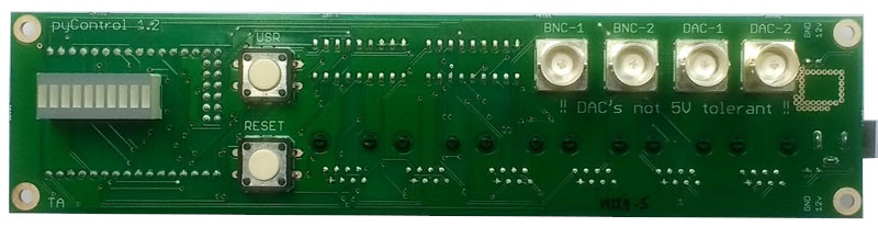 Breakout 1.2 Back:
class Breakout_1_2()
Atributes:
Breakout_1_2.port_1, ... , Breakout_1_2.port_6
Breakout_1_2.BNC_1, Breakout_1_2.BNC_2
Breakout_1_2.DAC_1, Breakout_1_2.DAC_2
Breakout_1_2.button
Example usage:
# Instantiate breakout board object.
board = Breakout_1_2()

# Instantiate poke connected to port 1.
left_poke = Poke(port=board.port_1, rising_event='left_poke')

# Instantiate digital output on BNC connector BNC_1.
BNC_output = Digital_output(pin=board.BNC_1)

# Instantiate digital input on BNC connector DAC_1.
BNC_input  = Digital_input(pin=board.DAC_1, rising_event='BNC_input')

# Instantiate analog input on BNC connector BNC_2.
analog_input  = Analog_input(pin=board.DAC_1, name='Analog 1', sampling_rate=1000)

# Instantiate pushbutton input, need to enable pullup resistor to use pushbutton.
pushbutton = Digital_input(pin=board.button, falling_event='button', pull='up')
Behaviour ports
Pinout
Each behaviour port is an 8 pin RJ45 connector (compatible with standard Cat 5 or 6 network cables), with the following set of lines:
| Function | RJ45 connector pin # |
|---|---|
| Ground | 2 |
| +5V | 6 |
| +12V | 8 |
| Digital input/output (DIO) A | 1 |
| Digital input/output (DIO) B | 4 |
| Power driver (POW) A | 3 |
| Power driver (POW) B | 7 |
| Special function | 5 |
Current draw
When connecting custom devices to behaviour ports it is important to consider the amount of current they will draw. Several factors limit the maximum current that can safely be drawn:
- Cat 5 network cable (used to connect devices to behaviour ports) uses 24AWG wires for each conductor. 600mA is a conservative estimate for the maximum safe current per conductor (see here).
- The ICs which control the driver (POW) lines (see below) can only sink a certain amount of current without overheating. The maximum safe current depends on the number of driver lines on a single IC that are on at the same time. Currents up to 200mA are OK irrespective of the number of driver lines on. The maximum current with 4 lines on continuously is 300mA, and with a single line 400mA. One IC controls the driver lines for ports 1-3 and annother for ports 4-6. For more information see this application note.
- The voltage regulator on the breakout board that powers the behaviour port 5V lines can source aproximately 300mA of current, which is shared by the 5V lines on all behaviour ports.
DIO
The behaviour port digital input/output (DIO) lines connect directly to pins on the microcontroller. All DIO lines can be used as either digital inputs or outputs. These lines use 3.3V logic but can generally be interfaced directly with 5V logic systems and are 5V tolerant. Some of the microcontroller pins on DIO lines have additional analog input/output or serial communication capability (see above).
POW
The power driver lines are for controlling loads that need higher currents or voltages than can be provided directly from a microcontroller pin. These lines are connected to low side driver ICs (datasheet) on the breakout board, which are in turn controlled by pins on the microcontroller. Low side drivers connect the negative side of the load to ground when turned on:
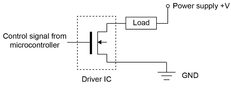
The positive side of the load can be connected to any voltage up to +12V. Each driver line can sink 200mA of current, with higher currents possible under some conditions (see above). The driver ICs are mounted in sockets and can be easily replaced if damaged. They have built in clamp diodes connected to the +12V supply so can be used directly to drive inductive loads such as solenoids.
The driver lines can be used as digital outputs by connecting them to a positive voltage via a pull-up resistor:
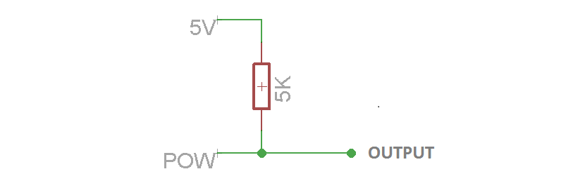
This can be useful if you need to control devices that require a digital logic signal with a voltage higher than 3.3V (though many 5V logic devices work fine with 3.3V inputs), or if you just need more digital outputs.
Inverted output
When using a POW line as a digital output using the circuit above, with the driver line (POW) off, the output will be pulled up to 5V. When the driver line is on, it will pull the output down to 0V. In your task code, to have the more conventional association of "on" meaning high voltage and "off" 0V, you can set the digital output inverted property to True. This change is particularly relevant if you want the POW pin's output voltage to be 0V when the task in not running, as all digital outputs automatically begin "off" when a task is uploaded and are turned "off" when a task is stopped.
Special
The special function pin has different functions on different ports, for example it may be an extra driver line or a pin with digital to analog (DAC) functionality, see above for more information.
Usage
Typically devices which plug into a behaviour port have several inputs and outputs, for example the Poke device comprises an IR beam, stimulus LED and solenoid. Rather than having to specify each input and output on a hardware device separately, each device has its own Python class which takes a behaviour port as an argument, allowing it to be instantiated with a single command. For example the hardware definition below specifies that 3 nose pokes are plugged into ports 1-3 of Breakout board 1.2.
from devices import *

board = Breakout_1_2()  # Instantiate the breakout board object.

# Instantiate the poke objects.
left_poke   = Poke(port=board.port_1, rising_event='left_poke'  , falling_event='left_poke_out' )
centre_poke = Poke(port=board.port_2, rising_event='centre_poke', falling_event='centre_poke_out')
right_poke  = Poke(port=board.port_3, rising_event='right_poke' , falling_event='right_poke_out')
The IR beam and solenoids on the pokes can be controlled from within a state machine as:
hw.left_poke.LED.on()   # Turn on the LED on the left poke.

hw.right_poke.SOL.off() # Turn off the solenoid on the right poke.
If you want to refer to a single pin on a behaviour port in a hardware definition, this can be done as in the examples below:
# Instantiate line POW_A on port 4 as a digital output.
house_light = Digital_output(pin=board.port_4.POW_A)

# Instantiate line DIO_B on port 5 as a digital input.
sync_input = Digital_input(pin=board.port_5.DIO_B, rising_event='sync_pulse')
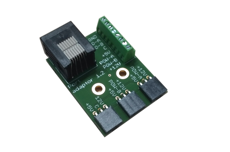
The easiest way to make an electrical connection to pins on a behavioural port is to plug in a port adapter board. This breaks out all the pins of the port to a screw terminal, and the power driver lines along with +5 and +12V to a set of female headers that can be used to connect loads such as solenoids or LEDs.
Port adapter: GitHub, Open Ephys, LabMaker
Interfacing with external hardware
Behavioural setups often comprise a mixture of pyControl hardware devices (see below) and external user-created or commercial hardware. Interfacing pyControl with external hardware requires both creating a physical electrical connection between the devices, and instantiating Python objects representing the device in the hardware definition or task file.
Options for creating an electrical connection are:
- The BNC connectors on the breakout board, which can be used for analog or digital input or output (see above). Each connector carries one signal line and one ground connection. They are often used for triggering external devices from pyControl or triggering pyControl events from external devices. They can also be used to output sync pulses for synchronising pyControl data with video or physiology data, as detailed in the synchronisation user guide.
- Connect to one or more lines on a behaviour port. The easiest way to do this is usually using the screw terminal connector on the port adapter board (see above). This is a good option if you need to connect multiple signals, and the 5V or 12V lines can be used to power small external devices. For example, we typically mount a port adapter board on the inside of the setup's sound attenuating chamber to control the house light, power the fan and send sync pulses to the camera, as shown here.
- Design a custom printed circuit board (PCB) with an RJ45 connector to connect to a breakout board behaviour port. This requires more work initially, but may make sense if you need to implement custom circuitry and want to scale to multiple setups. Complete design files for all the pyControl devices are in the hardware repository and provide a good starting point for thinking about your own designs. They were created in Eagle PCB, which is available as a freeware version (with a restriction on board size, but still sufficient for many applications) and also is free for academic use.
To define custom external hardware in your hardware definition or task file there are two options. The simplest is to instantiate the individual inputs and/or outputs directly in the hardware definition. These may be pyControl Digital_input, Analog_input or Digital_output objects (see above), or MicroPython objects; pyb.DAC for analog output, and pyb.I2C or pyb.UART for serial communication.
Alternatively, if an external hardware device comprises several inputs and/or outputs, or if there is additional code needed to control it, it may be worthwhile writing a Python class representing it. For example, the nose-poke device comprises an IR beam, a stimulus LED and a solenoid, all connected to a single behaviour port. You could instantiate and use the individual inputs and outputs like this:
# Instantiate inputs and outputs comprising a poke connected to behaviour port 1.
poke_IR_beam = Digital_input(pin=board.port_1.DIO_A, rising_event='poke_in')
poke_LED = Digital_output(pin=board.port_1.POW_A)
poke_SOL = Digital_output(pin=board.port_1.POW_B)

# Turn on and off the outputs
poke_LED.on()  # Turn on the LED
poke_SOL.off() # Turn off the Solenoid.
However the device has a Poke class representing it, defined in the file poke.py in the devices folder, which instantiates all the individual inputs and outputs as attributes, simplifying instantiating and using the device:
# Instantiate Poke object connected to behaviour port 1.
poke = Poke(port=board.port_1, rising_event='poke_in')

# Turn on and off the outputs, which are attributes of the Poke object.
poke.LED.on()  # Turn on the LED
poke.SOL.off() # Turn off the SOL
In addition to instantiating inputs or outputs, device classes can also contain code needed to control the hardware. For example the Audio_player class, defined in audio_player.py, instantiates a UART for serial communication with the module, but also has methods to send the serial commands needed to control the module.
Once you have written a file containing the class representing the device, put the file in the devices folder, then load your task or hardware definition to the board and the device driver file will be transferred automatically.
Devices
The following Python classes define devices which plug into behaviour ports. Device classes are defined in files in the devices folder, which are automatically transferred to the pyboard as needed when a task or hardware definition file is uploaded.
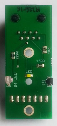
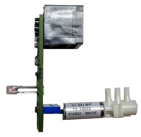
Poke
Nosepoke port with infra-red beam, stimulus LED and socket to connect solenoid valve.
| Front | Side - solenoid attached |
|---|---|
 |
 |
Mounted Front
Mounted Back

class Poke(port, rising_event=None, falling_event=None, debounce=5)
Arguments:
rising_event Name of event triggered on IR beam break.
falling_event Name of event triggered on IR beam make.
debounce Minimum time interval between events (ms), set to False to deactivate debouncing.
Attributes:
Poke.LED Stimulus LED
Poke.SOL Solenoid output.
Methods:
Poke.value() Returns True is beam is broken, False otherwise.
Example usage:
# Instantiate poke object and specify event names.
left_poke = Poke(port=board.port_1, rising_event='left_poke', 'left_poke_out')

left_poke.LED.on() # Turn on the stimulus LED.

left_poke.SOL.off() # Turn off the solenoid.
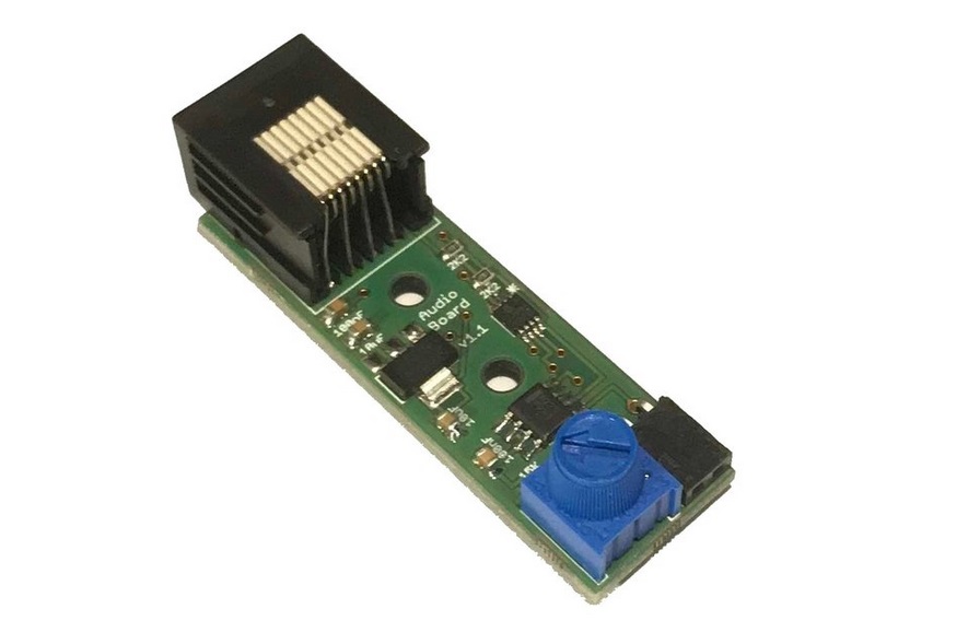
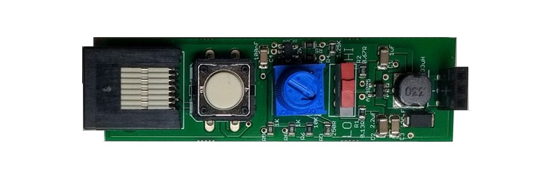
Audio board
Audio amplifier board for driving a speaker to produce auditory stimuli. The board uses the MicroPython DAC for stimulus generation. The audio board must be plugged into a port on the breakout board which supports DAC output and I2C serial communication (used to set the volume) - ports 3 and 4 on breakout board 1.2 are suitable.
In addition to the digital volume control there is a manual volume control knob (the small blue potentiometer on the board) that can be used to calibrate the audio volume.
class Audio_board(port)
Methods:
Audio_board.set_volume(V) Set volume of audio output, range 0 - 127.
Audio_board.off() Turn off audio output.
Audio_board.sine(freq) Play a sine wave at the specified frequency.
Audio_board.square(freq) Play a square wave at the specified frequency.
Audio_board.noise(freq=10000) Play white(ish) noise with specified maximum frequency.
Audio_board.click() Play a single click.
Audio_board.clicks(rate) Play clicks at specified rate.
Audio_board.pulsed_sine(freq, pulse_rate)
Play a sine wave of the specified frequency pulsed with a 50% duty cycle at the specified rate.
Audio_board.pulsed_square(freq, pulse_rate)
Play a square wave of the specified frequency pulsed with a 50% duty cycle at the specified rate.
Audio_board.pulsed_noise(freq, pulse_rate)
Play white(ish) noise with specified maximum frequency pulsed with a 50% duty cycle at the specified rate.
Audio_board.stepped_sine(start_freq, end_freq, n_steps, step_rate)
Play a series of sine waves whose frequency is stepped from start_freq to end_freq in n_steps steps at the specified step rate.
Audio_board.stepped_square(start_freq, end_freq, n_steps, step_rate)
Play a series of square waves whose frequency is stepped from start_freq to end_freq in n_steps steps at the specified step rate.
Example usage:
speaker = Audio_board(board.port_3) # Instantiate audio board.

speaker.sine(5000) # Play a 5KHz sine wave.

speaker.noise() # Turn on white noise.

speaker.off() # Turn off sound output.
LED driver
A constant current LED driver for optogenetic stimulation.
class LED_driver(port)
Methods:
LED_driver.on() Turn on LED
LED_driver.off() Turn off LED
LED_driver.pulse(freq, duty_cycle=50, n_pulses=False) Turn on a pulse train with specified frequency (Hz). The duty cycle (percentage of the period for which the signal is high) can be specified as 10, 25, 50 or 75. If the n_pulses argument is set to an integer the pulse train will stop after this number of pulses has been delivered.
Example usage:
stim = LED_driver(board.port_1) # Instantiate LED driver

stim.on() # Turn on continous.

stim.off() # Turn off.

stim.pulse(freq=20, duty_cycle=10, n_pulses=10) # Turn on 10 pulse train at 20Hz.
Stepper motor
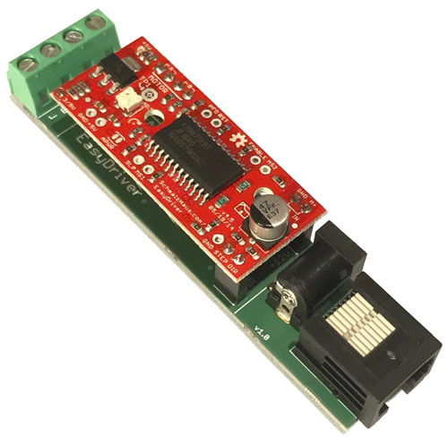
Class for controlling an EasyDriver stepper motor driver or any driver which takes a step and direction pin as control inputs.
The stepper motor adaptor board connects an Easydriver to a pyControl behaviour port. It can drive bipolar stepper motors with up to 750mA per phase. The maximum current can be adjusted from 150mA to 750mA using the potentiometer on the easy driver board. The stepper motor driver is powered with a 12V supply, but as it is a controlled current driver it can safely be used with lower voltage stepper motors as long as the motors maximum current is not exceeded. For more information see the Questions and Answers section of the EasyDriver documentation.
Maximum current
The stepper motor driver can draw power either from the 12V line on the behaviour port or from a 12V power supply connected to the stepper motor board using the 2.1 mm barrel plug. The maximum current that can safely be drawn from the behaviour port is 0.6A (the maximum rated current per conductor on Cat5 network cables). If your stepper motor requires more current, connect a 12V power supply directly to the stepper motor driver. The current requirements for some common stepper motors are detailed in the EasyDriver documentation.
class Stepper_motor(port=None, direction_pin=None, step_pin=None)
Methods:
Stepper_motor.forward(step_rate, n_steps=False) Turn the motor forward at the specified step rate (Hz). If the n_pulses argument is set to an integer the motor will move that many steps at the specified rate and then stop.
Stepper_motor.backward(step_rate, n_steps=False) Turn the motor backwards.
Stepper_motor.stop() Stop the stepper motor.
Example usage:
motor = Stepper_motor(board.port_1) # Instantiate stepper motor

motor.forward(step_rate=100) # Move forward at 100 step/second.

motor.stop() # Stop the motor.

motor.backward(step_rate=50, n_steps=100) # Move backward for 100 steps at 50 step/second.

motor_2 = Stepper_motor(step_pin='X1', direction_pin='X2') # Instantiating driver with step and direction pins rather than port.
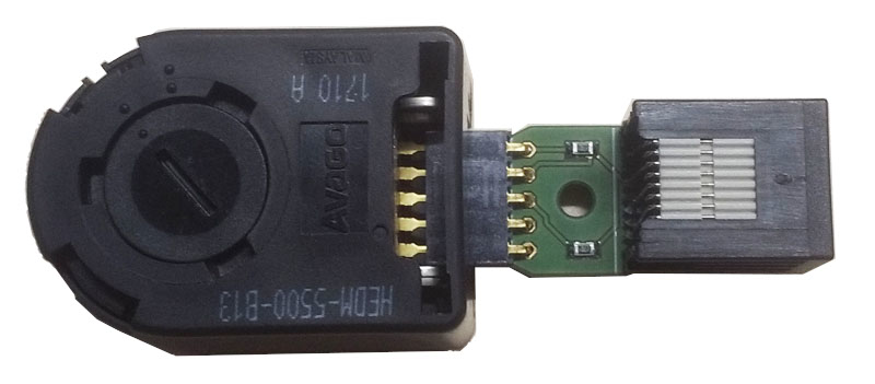
Rotary encoder
Class for acquiring data from a rotary encoder, used e.g. to measure the speed of a running wheel. The encoder must be an incremental rotary encoder that outputs a quadrature signal. The rotary encoder class streams the position or velocity of the encoder to the computer at a specified sampling rate, and can generate framework events when the position/velocity goes above/below one or more specified thresholds. Currently the rotary encoder class expects the two lines carrying the quadrature signal to be connected to MicroPython pins 'X1' and 'X2' (Port 1 DIO_A and DIO_B on breakout board 1.2).
The rotary encoder adaptor board connects an Avago HEDM-55xx series rotary encoder (datasheet) to a pyControl behaviour port. The rotary encoder adaptor must be plugged into port_1 on breakout board 1.2.
For an example task using a rotary encoder to measure running speed and trigger framework events when running starts and stops see running_wheel.
Decoding the quadrature signal from the encoder is handled by dedicated low level routines on the pyboard microcontroller, so load on the microcontrollers is not affected by the rate of edges generated by the encoder. The maximum rate at which edges can be registered is not specified but given the dedicated processing hardware is unlikely to be limiting in behavioural applications.
class Rotary_encoder(name, sampling_rate, output='velocity', threshold=None,
                     rising_event=None, falling_event=None, bytes_per_sample=2,
                     reverse=False, triggers=None)
Arguments:
name Name of the rotatory encoder, used to identify data files generated when input is recorded.
sampling_rate The rate at which encoder position/velocity is sampled.
output Whether to stream encoder position or velocity to computer. Valid values are 'position' or 'velocity'. Also determines whether a position or velocity threshold is used for event generation. Velocity signals are in units of encoder counts per second, so an encoder with a resolution of 100 counts per revolution turning at 2 revolution per second would output a velocity of 200. Position signals are in units of encoder counts.
threshold Threshold against which the position or velocity (as specified by the output argument) is compared for generating rising and falling events, must be an integer.
rising_event Name of event triggered when position/velocity crosses threshold in rising direction.
falling_event Name of event triggered when position/velocity crosses threshold in falling direction.
bytes_per_sample Number of bytes used per sample when data is sent to the computer. Valid values are 2 or 4. Only set to 4 if your signals are likely to go outside the range covered by 2 byte signed integers (-32748 to 32748).
reverse Set to True to reverse the direction of rotation which is considered a positive velocity.
triggers Used to specify multiple thresholds for generating framework events by passing in a list of Analog_trigger objects (see Analog_input docs above). If the triggers argument is used then the threshold, rising_event and falling_event arguments are ignored.
Attributes:
Rotary_encoder.velocity The current velocity of the encoder.
Rotary_encoder.position The current position of the encoder.
Example usage:
# Instantiate rotary encoder.  Encoder must be plugged into Port 1 of breakout board 1.2.
# Encoder is configured to report velocity at a 100Hz sampling rate and generate events
# 'running_start' and 'running_stop' when the speed goes above/below a threshold of
# 200 encoder counts/second.

running_wheel = Rotary_encoder(name='running_wheel', sampling_rate=100, output='velocity', threshold=200,
                    rising_event='running_start', falling_event='running_stop')

current_speed = running_wheel.velocity # Get the current speed of the encoder.
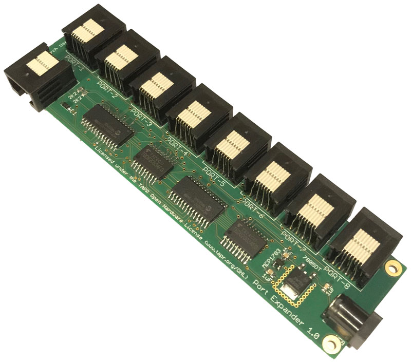
Port expander
The port expander board uses serial to parallel IO expander ICs (datasheet) to run 8 behaviour ports from a single behaviour port on the breakout board. The port expander must be connected to a behaviour port that supports I2C serial communication (ports 3 and 4 on breakout 1.2).
Each port on the port expander works like a standard behaviour port, with 2 DIO lines, 2 driver lines for high current loads, as well as ground, 5V and 12V lines. Digital outputs on the port expander do not support the Digital_output.pulse() method.
Maximum current
The port expander can draw power either from the behaviour port or from a 12V power supply connected to the expander board using the 2.1 mm barrel plug. The maximum current that can safely be drawn from the behaviour port is 0.6A (the maximum rated current per conductor on Cat5 network cables). If the devices plugged into the port expander may draw more than 0.6A current in total, connect a power supply directly to the port expander board.
class Port_expander(port=None)
Example usage:
port_exp = Port_expander(board.port_3) # Instantiate port expander.

poke = Poke(port=port_exp.port_1) # Poke conencted to port expander port 1.

house_light = Digital_output(pin=port_exp.port_2.POW_A) # House light connected to driver line A on expander port 2.

button = Digital_input(pin=port_exp.port_3.DIO_B, rising_event='button_press') # Button connected to DIO line B on expander port 3
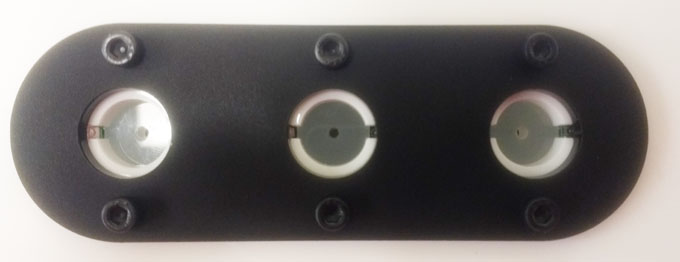
Five poke
The Five Poke board is a set of five nose pokes on a single PCB, each with an IR beam and stimulus LED. The Five Poke connects to 2 behaviour ports on the breakout board. Port 1 on the Five Poke must be connected to a behaviour port with 3 driver lines (port 1 or 2 on Breakout board 1.2). Port 2 on the Five Poke must be connected to a behaviour port with 3 DIO lines (port 3 or 4 on Breakout board 1.2). The events generated by the IR beam breaks are called 'poke_1', 'poke_2' etc. by default, and the events generated by the IR beam makes are called 'poke_1_out', 'poke_2_out' by default. Different event names can be specified when the Five poke is instantiated.
Five poke mounted
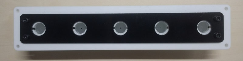
Five poke PCB
class Five_poke(ports,
    rising_event_1='poke_1',falling_event_1='poke_1_out',
    rising_event_2='poke_2', falling_event_2='poke_2_out',
    rising_event_3='poke_3', falling_event_3='poke_3_out',
    rising_event_4='poke_4', falling_event_4='poke_4_out',
    rising_event_5='poke_5', falling_event_5='poke_5_out',
    debounce=5)
Example usage:
# Instantiate Five Poke
# Port 1 on the Five poke board is connected to port 1 on the breakout board.
# Port 2 on the Five poke board is connected to port 3 on the breakout board.
five_poke = Five_poke(ports=[board.port_1, board.port_3])

five_poke.poke_1.LED.on() # Turn on poke 1's LED.
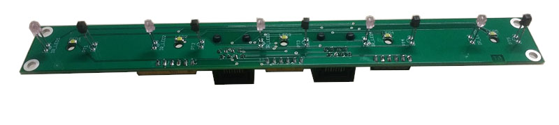
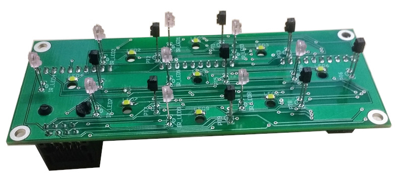
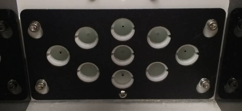
Nine poke
The nine poke board is a set of nine nose pokes on a single PCB, each with an IR beam and stimulus LED. The pokes are controlled from a single behaviour port using i2c serial communication (supported by ports 3 & 4 on breakout board 1.2). Events generated by the IR beam breaks are called 'poke_1', 'poke_2' etc. by default, and events generated by the IR beam makes are called 'poke_1_out', 'poke_2_out' etc. by default.
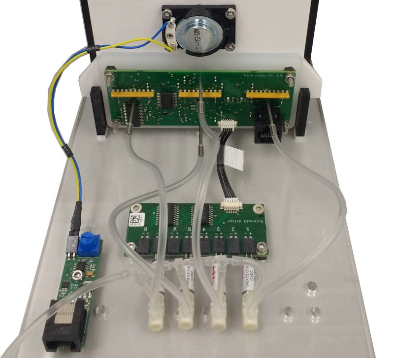
An optional solenoid driver daughter board can be connected to the nine poke board to control up to 8 solenoids. If the solenoid driver board is not connected, the solenoid_driver argument must be set to False when the Nine_poke is instantiated.
Nine poke PCB
Nine poke mounted
Back view showing solenoid driver board
class Nine_poke(port, rising_event_1 = 'poke_1', falling_event_1 = 'poke_1_out',
                      rising_event_2 = 'poke_2', falling_event_2 = 'poke_2_out',
                      rising_event_3 = 'poke_3', falling_event_3 = 'poke_3_out',
                      rising_event_4 = 'poke_4', falling_event_4 = 'poke_4_out',
                      rising_event_5 = 'poke_5', falling_event_5 = 'poke_5_out',
                      rising_event_6 = 'poke_6', falling_event_6 = 'poke_6_out',
                      rising_event_7 = 'poke_7', falling_event_7 = 'poke_7_out',
                      rising_event_8 = 'poke_8', falling_event_8 = 'poke_8_out',
                      rising_event_9 = 'poke_9', falling_event_9 = 'poke_9_out',
                      debounce = 5, solenoid_driver=True)
Example usage:
# Instantiate nine poke connected to breakout board port 3.
nine_poke = Nine_poke(port=board.port_3)

nine_poke.poke_1.LED.on() # Turn on poke 1's LED.

nine_poke.SOL_1.on() # Turn on the solenoid 1 output on the solenoid driver daughter board.

# Solenoids connected to the daughter board can be assigned to pokes:
nine_poke.poke_4.SOL = nine_poke.SOL_1 # Assign SOL_1 on the daughter board to poke 4.
nine_poke.poke_4.SOL.on()              # Turn on the solenoid that has been assigned to poke 4.
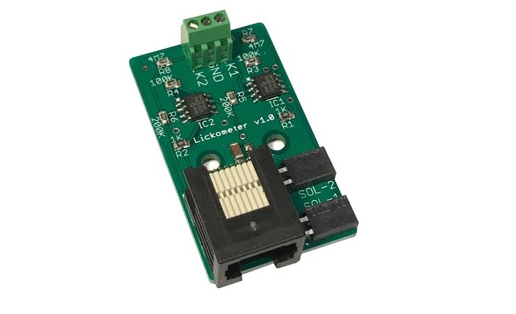
Lickometer
An electrical lickometer board which has two lick detection circuits and two solenoid ports. The outputs LCK 1 and LCK 2 should be connected to the reward delivery tubes and the GND output should be connected to the (conductive) floor of the setup. The lick detection circuits detect when the reward delivery tube is electrically connected to ground by the subject licking. The maximum current through the lick detection circuit is 1uA. The default event names generated by licking are 'lick_1' and 'lick_2' when the contact is made, and 'lick_1_off' and 'lick_2_off' when the contact is broken. Different event names can be specified when the Lickometer is instantiated. By default, debouncing is used on lick events with a 5ms debounce window.
class Lickometer(port, rising_event_A='lick_1', falling_event_A='lick_1_off',
                       rising_event_B='lick_2', falling_event_B='lick_2_off', debounce=5)
Example usage:
lickometer = Lickometer(port=board.port_1) # Instantiate lickometer.

Lickometer.SOL_1.on()  # Turn  on solenoid 1.
Lickometer.SOL_2.off() # Turn off solenoid 2.
Analog LED driver
An LED driver board with analog control of the LED current from 1 - 400mA using the MicroPython DAC. The Analog LED driver needs to be connected to a behaviour port that has a DAC output (ports 3 and 4 on breakout board 1.2).
class Analog_LED(port)
Example usage:
LED = Analog_LED(port=board.port_3) # Instantiate LED driver

LED.on(LED_current_mA=20) # Turn on the LED at 20mA current.
LED.off()                 # Turn off the LED
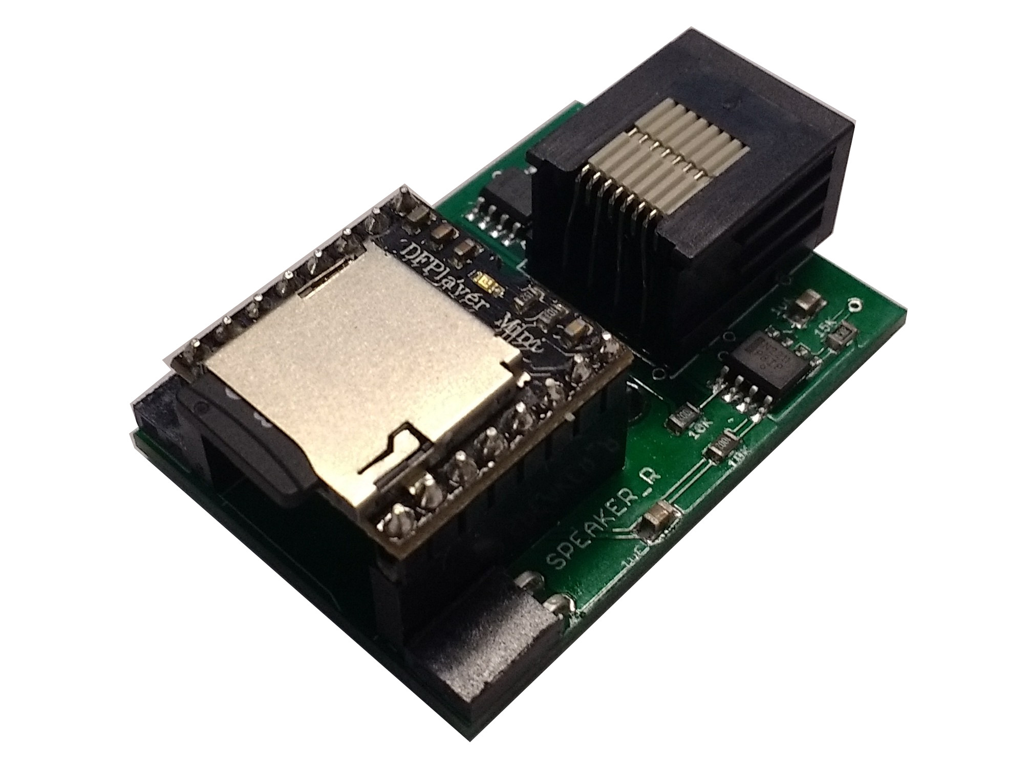
Audio_player
An audio board which uses the DFPlayer audio module to play .wav files from an SD card, allowing arbitrary audio stimuli to be presented. The board has two speaker outputs allowing stereo audio files to be played. Mono files are played from both outputs, but the amplifiers for each output can be independently enabled or disabled allowing files to be played from either or both speakers. The DFPlayer module requires the SD card to be formatted in FAT16 or FAT32 and expects a specific folder and file name structure - the folders must be named 01, 02 etc., and the files in each folder 001.wav, 002.wav etc. The Audio_player needs a behaviour port with UART serial connectivity so can be plugged into ports 1, 3 or 4 on Breakout_1_2. There is a short latency (approximately 15ms) between issuing the play command and the sound starting to play.
Sending multiple commands to the audio player without any delay in between (e.g. setting the volume and then playing a sound on subsequent lines of the task) may crash or fail because the audio player has not finished processing the first command when the second arrives.
class Audio_player(port)
Example usage:
player = Audio_player(port=board.port_1) # Instantiate Audio player

player.play(folder_num=1, file_num=2) # Play file 2 from folder 1.

player.stop() # Stop audio.

player.set_volume(12) # Set the volume (range 1 - 30).

player.set_enabled(left=True, right=False) # Enable left speaker output, disable right speaker output.
Load cell
A load cell amplifier based on the NAU7802 IC that can be used to take accurate weight or force measurements.
Note: The driver code for this device uses softI2C which requires a recent version of Micropython to work.
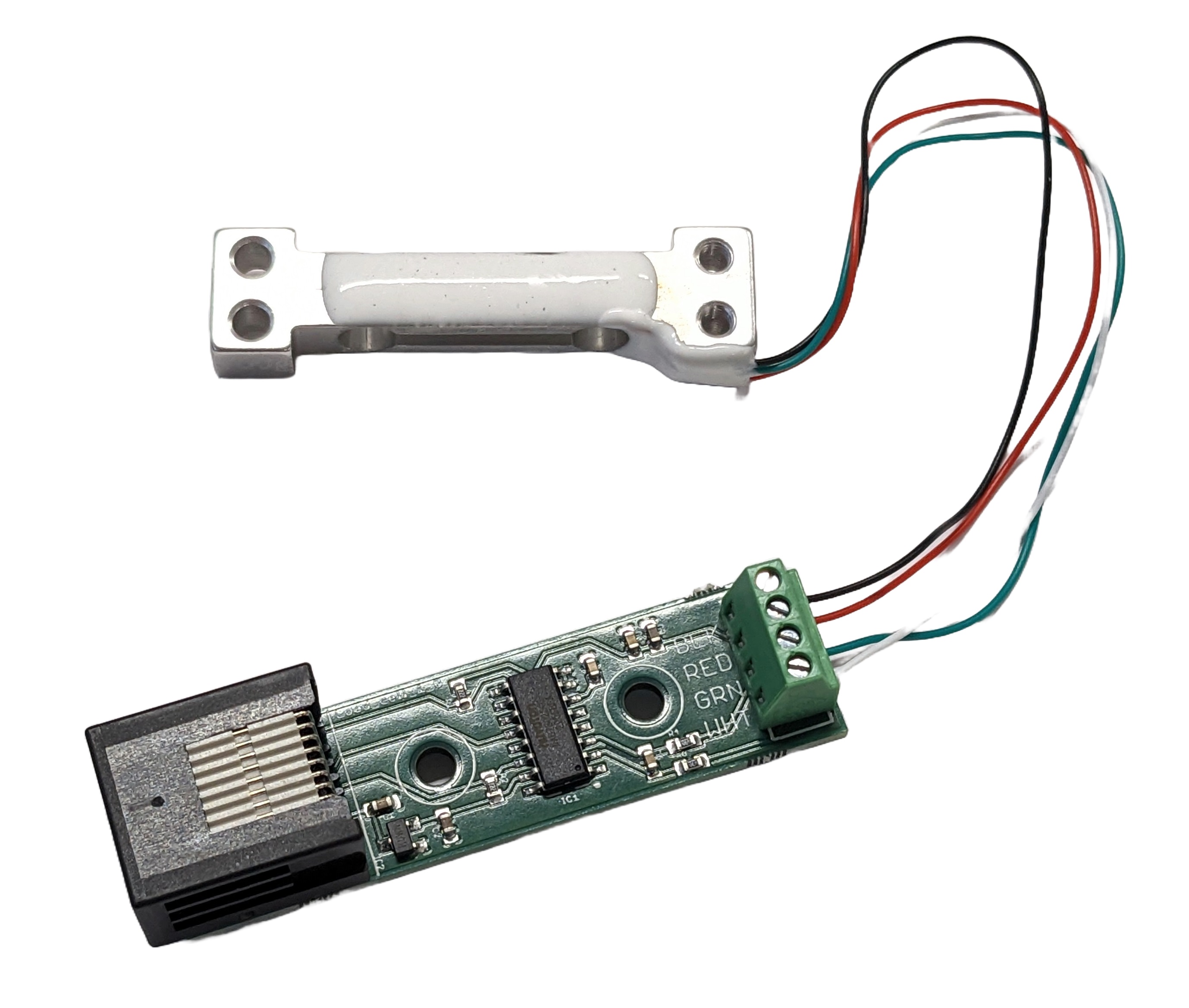
class Load_cell(port, offset=0, scale=1)
Example usage:
load_cell = Load_cell(port=board.port_3) # Instantiate the load cell.

load_cell.tare() # Set the zero point of the weight measurement.

load_cell.calibrate(weight=7.5) # Calibrate the load cell with a known weight.

weight = load_cell.weigh() # Take a weight measurement.
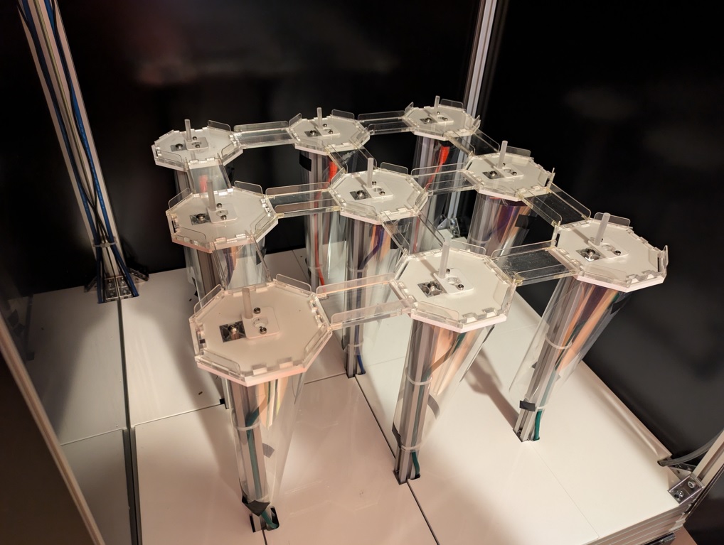
GridMaze
Gridmaze is a behavioural apparatus consisting of a grid of towers connected by removeable walkways to make a reconfigurable elevated maze environment. Each tower has a reward port with IR beam and solenoid for reward delivery, a speaker for playing auditory cues, and a stimulus LED for visually cueing locations. Two versions of the hardware have been developed, a small 3x3 grid maze and a large 7x7 grid maze. The grid maze is instantiated as a single hardware device. Rather than specifying all the poke in and out events manually in the task file, these are available as an events attribute of the gridmaze device which can be appended to the task events list. The events names are e.g. "A1_in" for a poke-in at tower A1, and "C2_out" for a poke-out at tower C2. The audio output uses the same commands as the Audio_board, e.g. noise, sine etc, but with additional commands to enable and disable the speakers on individual towers.
class GridMaze3x3()

class Gridmaze7x7()
Example usage:
from devices import Gridmaze3x3

maze = Grid_maze_3x3() # Instantiate grid maze device

events = ["user", "task", "events"] + maze.events # Append maze poke events to task events list.

maze.LED_on("A3") # Turn the tower A3 LED on.
maze.LED_off("A3") # Turn the tower A3 LED off.

maze.SOL_on("C1") # Turn the tower C1 solenoid on.
maze.SOL_off("C1") # Turn the tower C1 solenoid off.

maze.audio.set_volume(10) # Set the volume for audio stimuli.
maze.speaker_on("B2") # Enable the speaker on tower B2.
maze.audio.noise() # Play white noise from all towers with speakers enabled, see Audio_board for more stimuli.
maze.audio.off() # Stop audio playing.
maze.audio.sine(5000) # Play a 5KHz sine wave from all towers with speakers enabled.
maze.speaker_off("B2") # Disable the speaker on tower B2.
uRFID
Class for using the Priority 1 Design Micro RFID module to read FDX-B tags. The UART serial connection on the module should be connected to the DIO A and B pins on a port that supports UART (ports 1,3 and 4 on breakout board 1.2).
class uRFID(port)
Example usage:
rfid = uRFID(port=board.port_3) # Instantiate RFID module.

rfid.read_tag() # Return the ID of the most recent tag read, if no tag has been read return None.
MCP23017
The MCP23017 is a serial to parallel IO expander IC (datasheet) which can be used to add additional digital input/output lines to the MicroPython microcontroller. The IC must be connected to the MicroPython via an I2C serial connection, which are available on the DIO pins of ports 3 and 4 of breakout board 1.2. If you plan to use MCP23017 pins as pyControl digital inputs the INTA interrupt pin on the MCP23017 must be connected to a DIO pin on the MicroPython. The pins on the MCP23017 can be used as standard pyControl Digital_input and Digital_output objects as shown in the usage example below.
class MCP23017(I2C_bus=1, interrupt_pin='X5', addr=0x20)
Example usage:
mcp = MCP23017(I2C_bus=1, interrupt_pin='X5', addr=0x20) # Instantiate MCP23017.

mcp_output = Digital_output(pin=mcp.Pin('A0')) # Instantiate a Digital_output using pin A0 on the MCP23017.

mcp_input = Digital_input(pin=mcp.Pin('A1'), rising_event='event_A') # Instantiate a Digital_input using pin A1 on the MCP23017.
The MCP23008 IC is also supported using the same syntax. The MCP23017 has 16 DIO lines and the MCP23008 has 8 DIO lines.
class MCP23008(I2C_bus=1, interrupt_pin='X5', addr=0x20)
UART Handler
MicroPython compatibility
The UART_handler device requires MicroPython version 1.26 or newer.
If you need to update your MicroPython firmware, see Updating MicroPython for detailed instructions.
The UART_handler device generates a framework event whenever a UART message is received.
This removes the need for periodically polling the UART buffer to check for new messages, reducing latency and overhead.
After you attach the handler to the UART's RX interrupt, handle the emitted event like any other framework event.
Handle the event in your state machine's all_states function if you want to process all messages, regardless of the current state.
For devices sending UART messages to this handler, it is recommended to end the messages with a newline character (\n) and then use the uart.readline() method in the receiving code to read the message.
class UART_handler(event_name)
Arguments:
event_name The name of the event to generate when a UART message is received.
Example usage:
from pyControl.utility import *
from devices import UART_handler, Breakout_1_2
from machine import UART

board = Breakout_1_2()

handler = UART_handler(event_name="uart_message_received")

uart = UART(board.port_3.UART)
uart.init(115200, bits=8, parity=None, stop=1)  # configure the UART
uart.irq(trigger=UART.IRQ_RXIDLE, handler=handler.ISR)  # attach the handler to the UART


states = ["waiting_for_message"]
events = ["uart_message_received"]

initial_state = "waiting_for_message"


def waiting_for_message(event):
    if event == "uart_message_received":
        message_from_uart = uart.readline().decode("utf-8").strip("\n")
        print("Message from UART: {}".format(message_from_uart))